
Q-Sys | News

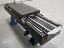
Single axis Motion Platform for a measurement application of large mirrors at synchrotrons
This high-precision motion platform is used by a synchrotron to measure mirrors with lengths varying from 100mm to 1400mm. This is done by moving the mirror back and forth in front of a laser interferometer. The base of the platform is a granite plate with an almost triangular shape. The interferometer is mounted on a hexapod that is located next to a precision linear axis. The guides, motor and optical encoder of the linear axis are mounted directly on the granite. This takes advantage of the extreme flatness of the granite, which means that parasitic errors are kept as small as possible. The axis has a stroke length of 1400mm with an accuracy of 5µm, a repeatability of 1µm and straightness and flatness less than 5µm.


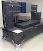
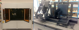
7-axis Motion Platform for an LTP/NOM application in a Synchrotron
In previous newsletters we have already mentioned LTP platforms that have been delivered to synchrotrons all over the world. In this case we are talking about a variant that is again slightly different. The basis is more or less our standard with 1500mm of travel on the longitudinal axis and 300mm on the transverse axis. The longitudinal axis has an accuracy of < 2µm after error mapping with parasitic angle errors (roll, pitch and yaw) of < 12.5µrad. In addition to the two linear axes, there is a so-called RTT (Rotary-Tip-Tilt) platform. This makes it possible to align the subject under test (SUT), to perform measurements at certain angles, to stitch together measurement results from more strongly curved SUTs and to completely flip it end-to-end to finish measurements without disturbing the stable environment. The repeatability of the Tip and Tilt axes is < 5µrad. The granite platform with the linear axes and the RTT platform were usually supplied as standalone platforms that could, of course, also be combined. This meant that both platforms had their own controller. In this case, all axes are combined in one controller. This enables the possibility to perform a coordinated movement with all axes, creating the option of “on the fly” measurements even with stronger curved SUT’s.

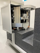
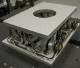
Extremely accurate 4-axis Motion Platform for a measurement application
This system is based on a large granite support structure comprising of a base plate onto which a column is mounted. The column serves as an air bearing guide way for a Z2 carriage that is driven by a ballscrew. At the top range of the Z2 travel an “in-line” external encoder is attached to provide higher accuracy position feedback. By measuring in Point of Interest (PoI) the accurary is improved due to absence of so called Abbe errors. Below the granite base a three axes (X Y and Z1) motion sub-system is located. A utility frame of structural Aluminium profiles encloses the three axes sub-system and provides support for ancillary functions like cable management and some pneumatic components. To provide for the vertical Z1 motion a triangular shaped granite slab is lifted up and down by three ballscrew actuators, one at each corner of the slab. Near each actuator there is also a linear encoder for accurate position feedback. By using three actuators a compensation of parasitical angular motion can be performed. On top of the granite slab a shuttle rides on air bearings in the XY plane. This shuttle is actuated by two independent perpendicular linear actuators. The ends of these actuators ride on vertically oriented granite guide planes through vacuum preload air bearings. The X and Y actuators are driven by linear motors and have their own local linear feedback devices to facilitate a robust start-up procedure. At some distance above the shuttle a metrology platform is kinematically attached to isolate it from mechanical stresses. This metrology platform supports two plane mirror interferometric sensor heads to provide for highest accuracy position feedback near the Point of Interest.

Two axes air bearing platform for a lithography application
This is a two-axis motion platform for a lithography application. The axes together perform a high-precision stepping and scanning movement, both with a travel of 600mm. For the bottom axis, the tracking error may be a maximum of 20nm at a constant speed of 50mm/s. While it is common in many cases to preload the air bearings with magnetic force, it has been decided here to do it with two air bearings preloading against each other. The reason for this is the specified tracking error. With magnetic preloading this could be exceeded due to hysteresis of the magnetic field in the preload strips. In this particular application, the top axis makes steps of 200µm with an accuracy of 20nm.

A second life for a glove box
This is an example where we have combined new parts with existing equipment. The customer was in possession of a glove box that should be reused. The new parts consist of a granite base, an XY system, two vertical axes and a new control system. Originally the glove box stood on a steel frame. In the new configuration, the glove box is mounted directly on a granite base. This choice was made because of the stability and the specifications that the positioning stages had to achieve. The consequence of this choice was that custom-made, gastight mounting devices had to be designed to mount the XY system inside the glove box but still directly on the granite. In short, no gas was allowed to leak from the glove box, but this method of mounting was also not allowed to negatively affect the specifications of the XY system. The accuracy of the positioning tables is better than 2µm (after error compensation) with a stroke length of 700mm x 300mm. The cables from the four positioning tables are led through the wall of the glove box to the control via gastight flanges. The granite base is larger than the glove box and offers the customer the opportunity to mount all kinds of process equipment, just like the glove box, on an extremely stable surface.

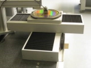
Both warm and safe
Invisible to the outside world, the motion platform is doing its job in the heated climate chamber. The printer in the climate chamber delivers the best possible product quality at an ambient temperature of up to 40°C. The heating is located on the roof, as are the filters that ensure that the air blown in is very clean. Filtration is done in a number of steps and the last one in it is a HEPA filter. To minimize energy consumption, a heat exchanger has been used that preheats the incoming air with the heat of the outgoing air. In addition to the axes of the motion platform, the control of the motion platform also regulates the temperature in the room. An additional advantage of using the climate chamber is that it also functions as a safety enclosure.

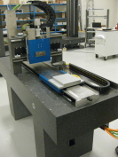
Integrated, ultra precise air bearing axis
This air bearing axis is integrated in a rectangular through hole in the granite base plate of a measuring system. The top of the base plate and one of the inner sides of the through hole form the guides for the air bearings. The carriage is driven by a linear motor and equipped with two linear encoders for feedback, in contrast to what is usual. Due to the fact that these encoders have an offset with respect to each other, it is possible to derive a parasitic angular error and, for example, to perform a linear correction in Point of Interest. In this case, this point is about 100mm in front of the carriage and about 300mm above the granite. With this configuration it was possible to achieve an accuracy of better than 0.5µm.

Dual axes optical metrology platform
In the final setup the platform will be combined with other equipment but consists of two parallel air bearing slides and is intended to perform characterization of optical components. In total the system has four moving slides because both metrology slides have a Cable Management Support (CMS) slide in order to decouple the cable management and to minimalize the influence of it. This solution enables a step resolution (Minimum Incremental Move) at nanometer level. The absolute positioning accuracy of the slides is better than 3µm over 1000mm of travel.
Base translation stage for a synchrotron
The base translation stage is part of a beamline tool that is used to investigate the internal 2D- and 3D-microstructure of complex, dynamic structures. This is all done at a micrometer scale within the same specimen quasi-simultaneously. On top of the base translation stage, various other stages and equipment are mounted with a total mass of approximately 3000kg. The consequence of stacking stages and equipment is that the Point of Interest (PoI) is relatively high above the granite carriage. In order to be able to perform the measurements in PoI with a high, repeatable accuracy, there are strict requirements for the repeatability of roll, pitch and yaw of the base translation stage. The specification was 15 µrad and in the final measurements the actual values turned out to be almost a factor of 5 below that. The result is much smaller Abbe errors in PoI and thus more potential for accurate measurements. These are impressive results, especially since the stage has a travel of over 1600mm. The stage is equipped with a double encoder, namely an incremental and an absolute. In addition, the stage has a pneumatic brake for in-position stability and a cover to prevent parts from falling inside and causing damage.
Ultra-precise three-axis motion platform
The title three axes motion platform does not do justice to the complexity of the concept. In fact, it is also incorrect because there are seven controlled axes. In terms of functionality, however, it concerns three axes. There are two vertically moving axes and on one of the two also moves a horizontal axis. The achieved absolute positioning accuracy for the three axes is 0.3µm over a stroke length of approximately 200mm and 100mm for the vertical axes and the horizontal axis respectively. However, the accuracy was not measured directly at the encoders, but in Point of Interest (PoI) and that is more than 120mm outside the platform. As a result of this distance, Abbe errors due to parasitic angle errors start to play a significant role. This is solved by driving the two Z-axes each with three motors and measuring the position with three linear encoders. This offers the possibility to correct the orientation of the carriage for the aforementioned parasitic angle errors and thus to optimize the positioning accuracy in PoI. The correction is optimal because all axes are equipped with air bearings resulting in repeating parasitic angle errors and making corrections very effective. The platform was designed in close collaboration with the customer, who was able to engineer his own part of the machine parallel to the development at Q-Sys. Finally, the two parts came together and could be combined into a working machine without any problems.
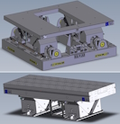
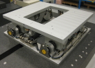
Motion platform with four degrees of freedom
The platforms in the photo are a clear example of reusing design concepts. Q-Sys is known for delivering bespoke platforms in which the requirements and wishes of the customer always come first. We always first shop in our large stock of proven concepts. This results in shorter lead times and lower costs for the customer. For example, the concept platform in the photo has already been delivered for a few different applications in different sizes, built of different materials and providing different performance. For instance, the smallest of the variants would fit on a desk while the mass of the largest is over 5000kg. Never hesitate to ask or challenge us with your requirements. We love to provide solutions for the most demanding applications.
Flexibility makes synchrotrons happy
Over the years, Q-Sys has supplied a large number of platforms to synchrotrons all over the world. These platforms seem identical at first glance, but nothing could be further from the truth. The concept is identical, but the platforms can differ from each other in quite a few aspects. These can be details such as the number of inserts and the location of the inserts in the granite, but the differences can also be more significant. These include the granite columns that can or cannot be removed or the height of the bridge. But also whether the platform has two axes (X and Y) or more. In the latter case, the axes can move in a coordinated manner. In addition, it is possible to equip the top axis (X) with a so-called lifter with which components can be manually aligned (both course and fine) in the vertical direction. The photo shows how the system is equipped with earth quake devices. The aim is to ensure that the platform does not move independently during an earthquake and that the loose granite columns remain in place. This facility has been developed in close collaboration with the customer and is another good example of what is possible.
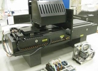
Motion platform for a 3D printer
The platform is the core of a 3D printer. It delivers 5micron positioning accuracy over the 1000mm x 200mm print area. Among other things, the platform is equipped with a vacuum chuck to “hold down” the printed products. The vacuum pump and all related components (e.g. checking if vacuum is present or not) are supplied on a dedicated bracket which can be integrated in a control cabinet. The print head bracket accommodates multiple print heads, each of which can be individually aligned to achieve optimum print quality. Next to the printing area is a station where a UV lamp fully cures the printed products. The two compartments are separated from each other by means of a pneumatically operated “light curtain”. In this way, UV light is prevented from accidentally reaching the print heads and clogging them.
Drop-in replacement XY
This XY table is a drop in replacement for an existing motion platform in a laser processing machine. For the customer, this meant that no mechanical changes were required to the machine. The new platform had (almost) the same dimensions and was mounted in the same place as the old platform. To get the ultimate accuracy from the machine, error mapping was performed using a 2D encoder. The big advantage of this is that the errors are measured in two directions simultaneously and not with a time difference as usual.
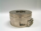
Precision direct drive rotary stage
This rugged 160mm diameter rotary stage provides excellent dynamic performance with minimal geometric errors. The combination of a direct drive servo motor, integral optical encoder and high performance bearings produces a stage with very high stiffness and zero backlash. With a 50mm through hole the stage is suited to a wide range of applications and is available with various configurations of limits and hardstops.
LTP for manufacturer of KB mirrors
KB (Kirkpatrick-Baez) mirrors are used in synchrotron research facilities and the techniques are pushing for smaller focused spot sizes. The KB mirror pairs are used to focus x-ray spot sizes down to below 1µm. When producing these mirrors it is important to achieve the extremely high specifications in both slope error and micro-roughness required. Nowadays the slope errors should better than 0.1µrad.
The LTP is able to precisely measure slope errors smaller than 0.1µrad along the whole mirror length. This single axis version of our proven optical metrology system used by several of the world’s synchrotrons is now used by a mirror supplier to validate surface profiles prior to delivery.
The system is available as a single axis platform but can also be delivered with additional axes. For example this could be an X2 axis for horizontal measurements but also a RTT platform for automatically alignment and flipping of the mirrors (SUT) without interference of an operator who could cause a thermal disturbance of the environment.
Positioning platform for aligning transfocators
A transfocator is a tunable X-ray focussing device based on compound refractive lenses. In synchrotrons these instruments can be used in both white and monochromatic beams to focus, pre-focus or collimate the beam. The transfocator needs to be aligned in four axes with respect to the beam. Q-Sys engineers have designed and built a motion platform for this specific purpose. The design is based on two drive wedges and one triangular opposing part. Each side of the system will have a combination of two drive wedges and one triangle. All elements can move by using recirculating bearings which provide high stiffness. The wedges are driven by means of ballscrews combined with stepper motors and a Harmonic Drive gear. All drive wedges are equipped with linear encoders to provide a very high positioning accuracy and a very small Minimum Incremental Motion (MIM). The platform has to carry a 400kg load and additionally a 200N external force acting at an offset. The footprint of the platform is less than 800mm x 600mm.
Solutions provided to synchrotrons to overcome challenges
Q-Sys engineers have been involved in synchrotron projects for more than 20 years. In many cases, the solutions offered have far exceeded expectations. In recent years, we have delivered a large number of motion platforms worldwide that are used in the metrology laboratories as LTP- (Long Trace Profiler) or NOM-benches (Nanometer Optical Measuring). There are variants of this platform with two (XY), but also with four or five axes (XY plus tip-tilt or XY plus rotary-tip-tilt). In addition to the offline equipment, we have also designed and supplied various solutions for the hutches. This includes detector positioning systems, stages for positioning transfocators and positioning systems for in-vacuum phase plates. The aforementioned is just a selection of the bespoke systems that we have designed and supplied and with these, Q-Sys has built a serious track record for synchrotron (test) applications.
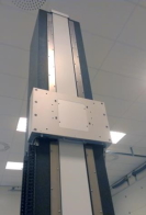
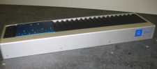
Long travel vertical air bearing axis
The air bearing axis is basically designed for vertical applications and offers travels of up to 2000mm. Actuation takes place by means of a ballscrew, whereby the position feedback is done with the aid of a high-precision optical linear encoder. These components are located in a slot in the granite column, which is then covered by a fabric belt. This prevents, on the one hand, contamination of for example, the encoder and, on the other hand, the possibility of touching the rotating spindle during movement or getting trapped. The roll and pitch errors of the slide during motion are smaller than 3arcs.
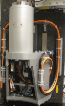
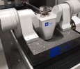
High-precision air-bearing movement for measuring optical components
The integrated rotation and vertical movement form only two axes in a four-axis platform. An air bearing vertical axis makes it possible to adjust the height of a direct-driven rotary table. This is necessary to bring an object to be measured in the correct position in relation to the measuring instrument. The rotary table is also equipped with an air bearing and is driven by a torque motor. The motor has no cogging and a torque ripple of less than 0.04%. This motor, combined with the air bearing and a non-contact optical position feedback, ensures an extremely small velocity ripple. The eccentricity of the rotation is < 0.1µm and the wobble < 1µrad. The center line of rotation is within 2µrad parallel to the vertical movement. The vertical axis is also equipped with air bearings and is driven by an epoxy core linear motor. As a result of the chosen motor concept, forces are only applied in the drive direction and this results in a pitch of < 8µrad and a yaw of < 3µrad. The total mass is balanced so that the motor generates a minimum of heat.
Linear positioning stage with up to 2000mm travel
Our QL-R range of stages has been extended—literally. This versatile stage is now available with travels up to 2000mm. Linear motor driven, the stages offer various combinations of motor size and encoder resolution to suit a wide range of applications. Internal cable management makes this a neat and compact stage, suitable for use in single or multi-axis systems. For more information about the stage please see the download section of our website.
High Accuracy Rotary-Tilt Axes for Laser Machining
The two axes use air bearings to provide highest possible accuracies. The precision-aligned axes can, for example, be combined with linear axes and in that configuration give customers high accuracy machining capabilities for complex 3D part geometries. The rotary features a direct drive and a high resolution encoder. This combination makes a wide range of speeds possible without sacrificing accuracy. The tilt axis allows ±100° of travel. The combination of high precision encoders and air bearings provide excellent accuracy and repeatability performance. The encoders are absolute thus preventing loss of position in case of an eventual power failure.
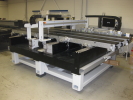
High Speed Test Platform
This three axis test rig delivers speeds up to 5m/sec over the central travel area with straightness and flatness within 5µm, making it ideal for print head testing. The reverse side of the granite bridge can also accommodate a full width axis to enable immediate optical inspection of the print output. Using a solid granite assembly, the stage is exceptionally stable and is fitted with linear motor drive for the horizontal axes.
Large scale motion platform for FPD laser processing
The platform was developed in close collaboration with the customer. It is built on a so-called polymer composite base. In addition to the three motion axes, the scope of supply included various other components that are necessary for the process. Examples are facilities for unloading and loading of the FPD, but also the alignment and inspection of the FDP, camera’s, sensors and extraction equipment. Special attention was required for the grippers with whom the FPD is clamped. This was a delicate process and damage to the FPD should be prevented at all times. The approximate travels of the axes are 1500mm x 1200mm with the achieved straightness and flatness of the movements being about 10µm.
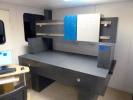
Bespoke development platform for 3D printing
This development platform is yet another good example of our bespoke service for non-standard motion systems. The platform is intended for use in a 3D printing application. It delivers 5 micron positioning accuracy over the 1000mm x 100mm print area and comes with a UV blocking safety housing. Among other things, the platform is equipped with a vacuum chuck to “hold down” the printed products. Next to the printing area is a station where a UV lamp fully cures the printed products. Inside the cabinet, all components are black, as far as possible, to avoid reflections of light and to prevent the printheads from clogging with cured ink.
Motion platform with 4 degrees of freedom (DoF)
This 4 axes platform provides motion for precision alignment as required in for example synchrotrons. It concerns horizontal and vertical adjustment plus rotation about these two axes. The travels are ±40mm for the linear motion ±1° for the rotations. The platform features an unusual three-wedge design to achieve the required motion in a very limited envelope. The through hole is 500mm x 300mm and allows access from both top and bottom.

Controller upgrade
While capital expenditure budgets remain under tight control, more users are finding that a new lease of life can be achieved with an overhaul of their existing hardware combined with replacement of the controls system with an up-to-date alternative. While motion stages have changed little in recent years, control systems are continually evolving. The latest system to receive such attention from Q-Sys is a laser cutting station where the motion stages and laser have many years of service left in them — replacing the old controller will increase reliability and extend the system usability for some time.
Motion and positioning system field support and upgrades
Q-Sys is pleased to announce a service and support facility for owners and operators of high performance motion and positioning systems. Following last year’s closure of Anorad’s European offices, existing owners of Anorad systems have very limited options for technical support – not a satisfactory situation for the large installed base in the UK and mainland Europe.
Q-Sys was formed in 2007 by four senior managers from Anorad to continue the tradition of designing and building high specification motion platforms. Alongside this expertise, Q-Sys engineers are familiar with the majority of system hardware in use in Europe and are able to provide a comprehensive maintenance and repair service. This can range from the occasional call to rectify a system problem - through routine planned maintenance for essential production machines - all the way to full upgrades and refits on older or more heavily used equipment. This can of course incorporate full controller upgrades to take advantage of the significant improvements in hardware and software in recent years. Sometimes this can be the cost effective way to keep a system running longer and delay the need for more significant capital expenditure on whole system replacement.
Service support can be arranged either on an as required basis or through a managed service contract providing scheduled service visits, with emergency call out if required.